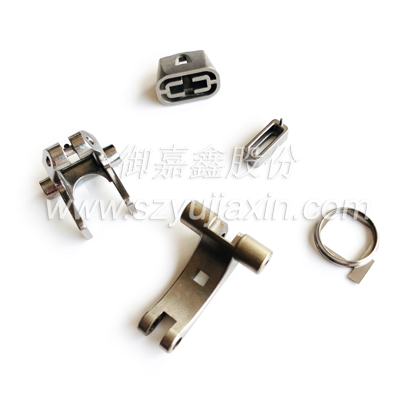
The design of MIM parts is similar to plastic injection molding.
Due to being not limited by traditional metal forming processes, part designers can use new perspectives to reimagine new parts from the beginning, envision how production processes can reduce material weight, combine multiple parts into one, or shape functional and decorative features.
To fully leverage the advantages of MIM technology and enhance processability in the design process of MIM parts (whether they are newly designed or replaced by parts produced using other processes), the following design criteria are proposed.
1 Process design
The simplest MIM parts are produced using a cavity formed by the combination of two half molds in a flat and enclosed manner.
Among them, the half mold is composed of a core with uniform gaps installed in the other half mold, and the uniform gaps left are used to form parts with uniform wall thickness.
The core molding is the internal structural features of the part, while the cavity molding is the external structural features of the part.
All structural features of the design must be formed parts that can be detached from the mold cavity and solidified from the core using a top rod.
When the complexity of MIM parts increases, sliders, cores, and other tools commonly used in plastic injection molding can be added to form them.
While increasing the structural features of the parts, the complexity of the parts also increases. At this time, by eliminating the operating costs of general and subsequent processing or assembly operations related to tools and technical equipment, MIM parts can gain economic benefits.
At every stage of design, these benefits and costs must be carefully balanced against each other.
When designing MIM parts, in order to fully benefit from this process, the following key points must be considered: uniform wall thickness, thickness transition section, core removal holes, demolding slope, strengthening ribs and spoke plates, chamfering and rounding, threading, holes and grooves, root cutting, pouring system, parting line, decorative features, sintering support, etc.
The following will explain separately.
1.1 Uniform wall thickness
If possible, the wall thickness of the entire MIM part should be the same. Different thicknesses can cause distortion, internal stress, porosity, cracking, and dents. Additionally, it can lead to uneven shrinkage, affecting dimensional tolerances and control.
The thickness of the parts should be within the range of 1.3-6.3mm.
In order to achieve uniform wall thickness of MIM parts, several commonly used methods for changing shape are provided.
1.2 Thickness transition section
In some cases where wall thickness uniformity cannot be achieved, a gradual transition should be designed between different thicknesses.
1.3 Core removal holes
The use of core removal holes can reduce the cross-sectional area to within the standard limit, achieve uniform wall thickness, reduce material consumption, and reduce or eliminate cutting operations.
The priority direction is parallel to the direction of the mold opening, in other words, perpendicular to the parting line.
Because the core rod is supported at both ends, it is best to use through holes instead of blind holes, which use cantilever rods.
1.4 Demoulding slope
The demolding angle is a small angle on the surface that needs to be parallel to the direction of movement of the model part.
For the core rod, it needs to be particularly precise.
The demolding angle is for the convenience of demolding and ejecting molded parts. The demolding angle is generally 0.5 to 2 degrees. The actual demolding angle increases with the depth of the formed holes or recesses, as well as the complexity of the parts or the number of cores.
1.5 Strengthening ribs and spoke plates
Strengthening ribs and plates are used to reinforce thinner walls and avoid thick sections.
In addition to increasing the strength and stiffness of the wall thickness, it can also improve the material's flow and limit distortion.
The thickness of the reinforcing ribs shall not exceed the thickness of the adjacent walls. Thick reinforcing ribs are required structurally, and multiple reinforcing ribs should be used instead.
Recommended ratio of reinforced ribs. How to use reinforced ribs and cored holes to reduce weight while maintaining the functional strength of the parts.
1.6 Chamfering and rounding
Chamfering and rounding can reduce the stress at the intersection of structural features; Eliminating sharp corners that may cause cracking and corrosion of model structural features facilitates the flow of injection material into the model and helps the parts to detach from the mold cavity, which is conducive to the progress of molding operations.
1.7 Thread
Both internal and external threads can be formed using MIM technology, but compared to unscrewing the core, threads tapped with a tap are more precise and cost-effective.
In order to remove the model components that have twisted out the formed threads, it is best for the external threads of the formed thread model to be located on the parting line of the model construction.
In order to maintain the thread tolerance of the thread diameter, it is generally stipulated to have a small plane of 0.127mm on the parting line, which can ensure proper sealing of the model, reduce the traces of the parting line, avoid burrs at the root of the thread, and thus reduce the maintenance of the model.
1.8 Holes and slots
Holes and grooves, in addition to reducing part quality and forming uniform wall thickness, are also useful functional structural features of MIM parts, and generally do not increase part prices.
However, adding holes and slots will increase the complexity of the mold, which requires an increase in mold costs. Holes perpendicular to the parting line are the easiest to form and have the lowest cost. Holes parallel to the parting line, although easy to form, require the addition of sliders or hydraulic cylinders, which will increase the cost of early mold manufacturing.
The internal connecting holes can be formed.
If possible, a hole should be made into a D-shaped hole to create a flat surface on the core rod, thereby enhancing the sealing of the mold. Otherwise, it is necessary to make a curved surface of the matching parts, and the thin cutting edge will cause abnormal wear.
1.9 Root cutting
Using split type molds, external root cutting on the parting line is easy to form. Manufacturing this shape requires adding mold parts, increasing mold costs, and reducing productivity.
Some internal root cuts can be made using sliders, while others can be formed using movable cores.
In most MIM part designs, designers may decide to cancel internal root cutting due to increased costs and the possibility of flash edges.
1.10 Pouring system
Injectable materials enter the mold cavity through gates. Due to the high metal content of MIM injection materials, these gates of MIM are generally much larger than those of plastic injection molding.
Due to the fact that gates usually leave marks where finished parts come out of the forming cavity, the setting of gates needs to balance the required craftsmanship, functionality, size control, and aesthetics.
It is best to set the gate on the mold parting line, as shown in Figure 10, so that the flow path of the injection material can impact the mold cavity wall or core rod.
In addition, for parts with different wall thicknesses, the gate is usually set at the thickest cross-section to allow the injection material to flow from the thick section to the thin section. Setting the gate in this way can eliminate holes, grooves, stress concentration, and streamlines on the surface of the parts.
If you want to produce parts with multiple cavities, you must also consider the size and setting of the gate to ensure that the amount of injection material supplied to each cavity is the same while maintaining a balanced filling rate.
1.11 parting line
If possible, the orientation of all structural features should be perpendicular to the parting line, so that the formed parts can be removed from the mold.
Usually, the parting line is transformed into a proof line on the surface of the part, which is the inevitable result of combining two half models.
In the upper half of the model, the geometric shape of the entire part is formed, and at this point, the parting line can only follow the bottom edge of the part without generating a parting line. Normally, the model can be designed to separate along inconspicuous edges, thereby hiding the parting line.
It is best to place the parting line on a plane, but sometimes, in order to achieve the required structural features for molding, it is necessary to change the simple shape.
Increasing the complexity of the parts may increase the manufacturing and maintenance costs of the mold, but when pouring the structural feature into shape, the cost may be reduced. Otherwise, cutting or assembly operations may be required.
1.12 Decorative features
Marking, embossing, identification of part numbers, mold numbers, and hole numbers are all easily formed in appropriate positions on the parts without increasing the cost of the parts.
These features can make prominent or concave, and MIM technology can produce high-level feature details, including sharper diamond embossing.
1.13 Sintered parts support
During the degreasing and sintering process, the raw MIM parts shrink by about 20%. In order to minimize the possible twisting deformation, appropriate support must be provided for the MIM parts during sintering.
Usually, MIM parts are placed on flat ceramic or pallets.
It is best to design the flat or tray used for sintering to have a large plane or a plane with several common structural features of the parts, so that standard brackets can be used. MIM parts with long spans, cantilevers, or vulnerable areas may require specialized brackets or fixing devices to support them. These production costs are all very high.
II Subsequent processing of sintering
Given that the tolerance of MIM process is between ± (0.3% -0.5%), many parts have been sintered to the final size. If the tolerance of a certain structural feature of the part is relatively tight, subsequent mechanical processing can be carried out.
MIM part materials can be cut, threaded, drilled, pulled, ground, or welded like forged parts.
In order to improve the strength and wear resistance of the hardness tester, MIM parts can also undergo heat treatment.
In addition, due to the fact that MIM parts typically limit the interconnected porosity to below 0.2%, special surface preparation is not required for routine coloring and electroplating.
III Conclusion
As a new type of forming technology for powder metallurgy parts, parts have evolved from experimental development of individual and few parts to a stage of large-scale production after decades of development.
The trend of MIM parts development in North America can be clearly seen from the annual powder metallurgy parts design award winning MIM parts projects held by MPIF.
From 1997 to 2001, MPIF awarded 15-18 parts annually in the powder metallurgy parts competition. In the category of award-winning parts, MIM has been used from 1997 to 2004, but since 2005, award-winning MIM parts have been divided into seven categories: aerospace/military, medical/dental, manual tools/entertainment, electronics/electrical, hardware/appliances, industrial motors/control devices, and other categories.
These indicate that the production of MIM parts has entered a gradual development stage in North America.
In Chinese Mainland, thanks to the strong demand of electronic digital products for MIM parts, large and small MIM enterprises are distributed throughout the country, concentrated in the Yangtze River Delta, Pearl River Delta, Beijing and surrounding areas. It is urgent to vigorously promote the basic knowledge and production application of MIM parts in Chinese Mainland, especially in more fields.